
PROJECTS

437 MHZ CROSSED YAGI
Firstly I would to thank the following people for help with this project:-
KC4UMO Buddy McLawhorn:- For taking the time to answer some questions.
G4YCA Chris:- For his webiste article on the construction of the Power Divider/Splitter.
VK4ZZ Gavin:- For the use of the analysers.
I have built a few J-poles, verticals etc, but this was first stab at building a Yagi, various lessons have been learned, and as usual the second one is easier than the first. Well here goes:-
I developed an interest in working the birds, so I started to look for crossed yagi’s on the internet. After a few days I decided to build my own. I used a java based website to get my element dimensions and spacing.
Specs
Ref. 337mm, DE. 322mm, D1. 298mm, D2. 294mm, D3. 290mm, D4.286mm, D5. 283mm, D6. 280mm, D7. 277mm,
Spacing (Cumulative)
Ref. Zero DE. 137mm, D1. 188mm, D2. 311mm, D3. 458mm, D4. 629mm, D5. 821mm, D6. 1027mm, D7. 1242mm.
I included an extra 40mm each side of the boom for waterproofing purposes. The vertical side of the array was placed ¼ wavelength in front of the first, so an extra 171mm was added to the total. (171mm, ¼ wavelength at design frequency of 437.800 Mhz).
When measuring for the holes in the boom I found that two elements intersected each other, no drama, a shift of a few mm both ways fixed this. I modeled the array in EZNEC, and the change was not even noticeable.
Both antennas would be fed using a pair of gamma match’s, and a phasing harness. (more on that later). The material I chose to use was as follows:-
Boom:- 20mm aluminum box section, 3mm thickness (I had a choice here but later regretted this decision), the other alternative was 25 mm box section with 1.9mm thickness.
Driven element was 10mm solid aluminum rod, and all the parasitic elements were 6.35mm solid aluminum rod. Living here in North Queensland (during the build) can be a pain as we are limited to what we can get, not what we want. I also chose to have all the elements insulated from the boom. This proved a challenge at first, but after a bit of hunting I found two sizes of plastic LED inserts that fit perfectly. The LED insert for the 10mm rod had to be cut in order to fit into the 20mm box section. This was no problem at all. Below is a photo of the LED inserts, note the larger (10mm) which shows cut to size.
I started with a test piece of the boom as shown below in order to see if everything worked as planned.
The boom was drilled using a drill press for accurate ling ups, elements cut to size, and LED iInserts trimmed. It was time to put it all together.
Gamma Match
This was made using striped 213 coax, 10mm aluminum tube (perfect fit with the coax), and copper strip cut to size to form the shorting bar. I made two brackets using 2mm aluminum flat bar, drilled and bent to hold the BNC connectors. I also used the same 10mm tube for the gamma tube. Hardware was 3mm stainless bolts to hold it together.
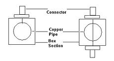
The phasing harness was made with quad shield RG6. Being the first one I have made, this took me some time to get it right. When the array was finished I found that the excess coax altered the VSWR a fair bit, depending where it was positioned. So I did some more research on the net, and found Chris’s (G4WYA) website, which showed how to build a power divider/splitter using aluminum box section and copper pipe. He even had the formula, so you could make your own out of what ever size material you can get. This is where I should have used 25mm box section with 1.9mm wall thickness.
The Formula
138Log10(1.08*D/d)
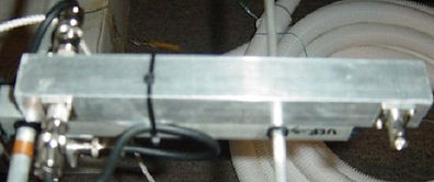
Where “D” is the inside dimension of the box section, & “d” the outside diameter of the copper tube. After plotting it on a spreadsheet, I found that for my case the 25mm box section and the standard copper water pipe of 12.7mm would of given me approx 35.3 ohms, not bad from target of 35.35 Ohms. However I only had a small section of 25mm x 1mm box section & 12.7mm copper pipe. I did not want to send 40 dollars on a new length of box section just for this purpose. End result, the VSWR on the divider is 1:1.5, happy here. Below is an image of the completed divider.
As mentioned I used EZNEC to check the antennas before I did anything. I lost around 3db when crossing the antennas, final output was an estimated 11.25 Db. The radiation pattern is pretty good considering I want this array to be close and not pin point down a rifle barrel.
The final assembly showed good bandwidth and a VSWR of 1:1.5, once again happy here. I used an MFJ & AEA analyser for this. Big thanks for the use of these pieces of equipment from fellow hams in Townsville.
Last but not least, I purchased some 6 & 10mm plastic caps to put over the ends of the elements, just to finish it off.
POWER DIVIDER / SPLITTER
As mentioned in my 437 Mhz antenna project, thanks goes to Chris G4YCA for his website details on how this works, complete with instructions.
Heres how I made mine!
The material I used was 25mm x 1mm Aluminium box section and 12.7mm copper water pipe. I chose to use BNC connectors on my 437Mhz yagi, however on my VHF yagi I plan to use N connectors.
I first measured and cut the copper pipe to a ¼ wavelength of the frequency I wanted including 10mm extra either end. I marked the ¼ wavelength on the pipe and drilled two holes. One hole was straight through on one end and the other was only drilled through one side
Make sure the hole size fits the terminals of whatever connectors you choose. Now prepare the box section, make sure it’s a little longer to fit the connectors and allow some room for what ever method you use to waterproof the ends. I used two part epoxy putty. Before your final assembly, fire up the soldering iron and tin all the points inside the copper pipe.
Next mount one of your antenna feed connectors to the box section, then slide in the copper pipe. Align the hole you drilled straight through to fit into the terminal of the connector, (you can hold this in place with hobby putty if you like). Now fit the other antenna feed connector again aligning the connector terminal to the whole. (If you used something to hold the copper pipe in place you can now remove it. Lastly fit the final connector and align to the single hole. Make sure it looks all even before you solder the copper pipe to the connectors.
Lastly waterproof the ends of the box section and the connectors where they meet the box. Time for testing
Formula
Again thanks to Chris G4YCA for the info
Use this formula to work out what sizes of material you can use to obtain the closest match. This would depend as in my case what was available.
138Log10{1.08D/d} Where “D” = Inner dimension of the box section & “d” = diameter of the tube.
GROUNDING STATION
I have a quite a few coax cables and various other cables coming down the outside wall of my house that enters the shack. Of course the wall had to be double besser brick with cavities filled with concrete so it was a job drilling two 40mm holes that length. I hired a Hilti drill and a special hole saw and away I went.
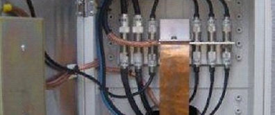
On the rear of my radio bench in the shack I have attached 12.7mm (1/2 inch) copper water pipe along the entire length; it is mounted on wooden standoffs. From here all of my equipment in the shack is connected using shield from RG 213, and connected to the copper pipe using stainless hose clamps.
From the point where I drilled the holes through the wall I attached a length of 50mm flat copper strip which goes out into the rear of my grounding station. From this point, the strip is connected to a piece of angle where all of my coax connectors are installed. (a junction before it comes into the house). The copper strip then runs out down the bottom of the station through 50mm pressure pipe and finally connects to various earth rods hammered into the ground. A total of four earth rods are used spaced equally apart.
I used a waterproof plastic electrical junction box mounted and sealed to the wall to keep the critters out. All the cables coming down the exterior wall of the house are enclosed in 50mm pressure pipe (to keep the XYL happy) It has to look neat!!!.
All the connections are lubricated with Penetrox A compound, and a large bag of silica gel crystals placed inside to keep the moisture at bay.
If that wasn’t good enough for the XYL, now I have to paint it the same colour as the house. Does it ever end!!.
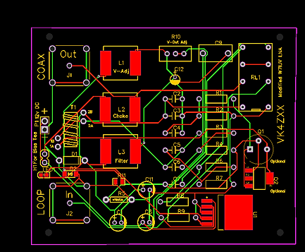
Low Noise Amplifier based on W7IUV Design
I have dedicated a seperate page for this project. A modified version. This project is still under way.
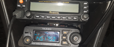
FTM-10SR TO TINY-TRACKER APRS
Successfully interfaced a Yaesu FTM-10SR (Motor Cycle version) with a Tiny Tracker for APRS use. I could not find any info on the internet regarding the interfacing, so after some time and study, it is now up and running.
Check my blog section and gallery for further details.
One trap I did come across and took a bit to figure out was that what ever wire you choose for the 'Carrier Detect' make sure you change the radio's menu item regarding the speaker output to Rear, Both or all.
Because the FTM-10SR has stereo output and also a speaker in the head unit, this makes sure the signal 'Audio' gets to the tine tracker.